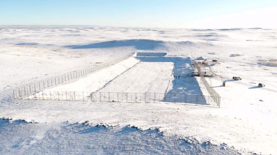
This project covers the surface component of the fuel system that delivers diesel underground to Shaft 1 Shops. This facility includes a fuel unloading area, fuel storage area and associated tanks, piping, and pumps.
This project also covers the borehole that diesel flows through to reach the Shaft 1 Shops underground fuel infrastructure.
GENERAL
The Shaft 1 Shops Fuel Delivery System is located in the north of Shaft 1. This facility receives and stores diesel prior to its batched delivery to the underground fuel tanks located within Shaft 1 Shops.
Fuel Unloading Area
The Fuel Unloading Area consists of a tanker unloading slab and an equipment island featuring the following items:
· Local control panel
· Unloading hoses, valves, and pipework
· Spill containment kit
· Portable eyewash unit.
The pumps, filters, and instruments associated with fuel unloading are housed within the adjacent Fuel Storage Area Fuel are delivered to the site in B-double tankers which is a park on the tanker unloading slab. The tanker operator connects the unloading hoses and commences the fuel unloading operation from the local control panel. The facility is utilized as an automated control system.
Fuel Storage Area
The Fuel Storage Area consists of an unbunded slab that falls across to the existing bunded lube storage area. This slab is supports the 90,000 L self-bunded fuel storage tank and the equipment enclosure which houses the batching tank and all of the pumps, filters, and instruments associated with fuel unloading and batching.
Unloaded fuel is pumped into the storage tank. Fuel from this tank is transferred underground as required via a batching process. The batching process involves pumping a small volume (~4,500 L) of fuel into the batching tank (located on the surface) and then releasing this fuel (by gravity flow) to the underground tanks via the Fuel Drop Line (refer Section 2.3). The facility is utilized as an automated control system.
Fuel Drop Line
The Fuel Drop Line takes fuel from the surface to the Shaft 1 Shops infrastructure located approximately 1,300 m underground. The dropline consists of an outer borehole casing and an inner fuel pipe that is grouted into the casing.
The fuel pipe selected is rated for the hydrostatic pressure that would occur if the line was filled with liquid. This scenario is however not part of the normal operating principle of the system. An accumulator installed as part of the underground fuel infrastructure is accommodate pressure surges.
Light Vehicle Refuelling Area
The Light Vehicle (LV) Refuelling Area consists of a refueling slab and an
equipment island featuring the following items:
· Fuel dispenser with flow meter and fuel master system
· Spill containment kit
· Portable eyewash unit.
The pump associated with LV refueling in located at the Fuel Storage Area inside the fuel storage tank (refer Section 2.2).
Light vehicle operators park on the refueling slab, log into the fuel master system and refuel their vehicle using a standard nozzle. The facility is utilized as an automated control system.
Interconnecting Pipework
Pipes that connect the unloading area, storage area, LV refueling area, and drop line are insulated carbon steel type and routed above-ground along with strip footings. Vacuum breakers are included in the batching circuit upstream of the Fuel Drop Line.