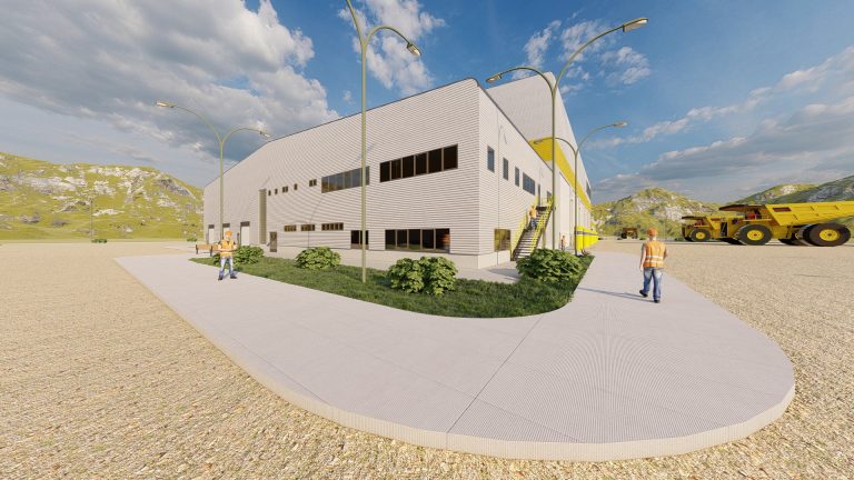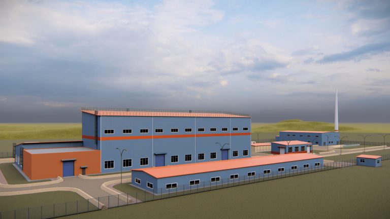

The Oyu Tolgoi complex is situated 550 km south of Ulaanbaatar, Mongolia’s capital, in the Aimag (province) of Ömnögovi, the South Gobi region of Mongolia which forms the border with China.
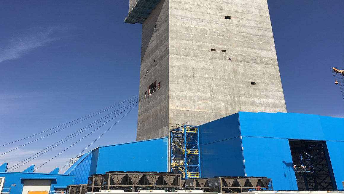
Headframe project is one of the biggest project constructed in Oyu Tolgoi project site.
General
The Oyu Tolgoi Shaft No 2 is a vertical downcast ventilation shaft. The shaft is a 10 m finished diameter monolithic concrete-lined shaft and sunk to a depth of approximately 1284.2 m below the shaft collar.
The shaft configuration is accommodated five (5) separate hoisting compartments. Two (2) compartments are allocated to the Production Hoist, two (2) compartments are allocated to the Service Hoist and the remaining compartment is allocated to the Auxiliary Hoist.
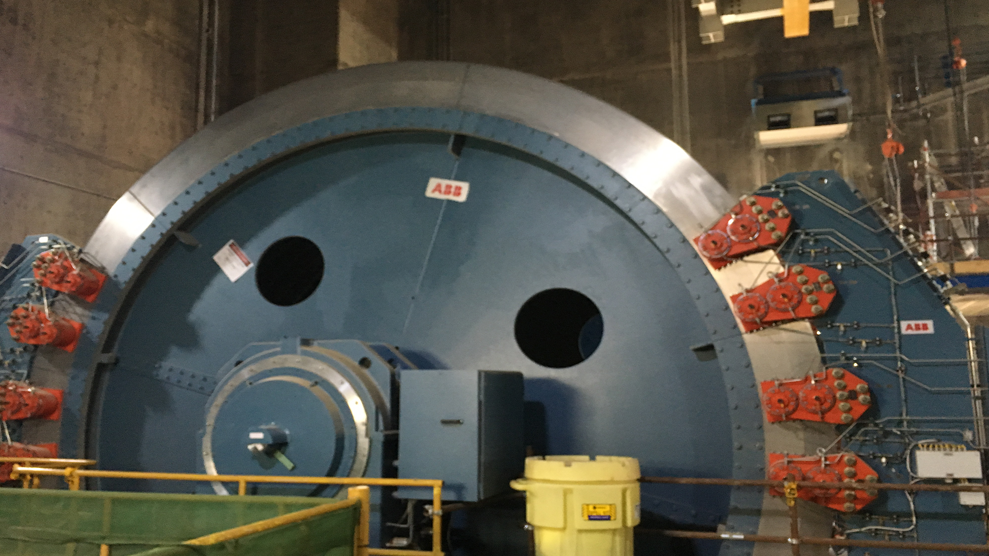
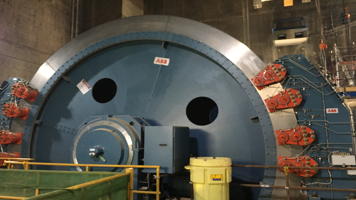
Production Hoist System Setup
The Oyu Tolgoi Shaft No 2 Production Hoist is a tower-mounted friction hoisting system contained within the concrete headframe structure. The hoist and the relevant ancillary equipment are installed on Production Hoist deck, EL. +78.500m.
The Production Hoist is hoist ore/waste rock using two (2) 60-tonne payload bottom-arc gate-type skips hoisting from a depth of EL. -1202.200m at a hoisting speed of 16.38m/s.
These skips are operated in 180mmx180mm hollow sections fixed steel guides.
The skips are loaded with ore/waste rock on Skip Loading Level (EL. -1202.200 m) by means of a high-speed loading conveyor via a shuttle car and chute. The skips are transported the ore/waste rock up the shaft to Dump Level (EL. -4.100 m) where the ore is discharged by means of skip dump rollers, fitted to the skip bucket, passing directly into a mechanical skip tipping mechanism (scrolls)
The Production Hoist is equipped with one (1) Ø 6.75m hoist drum capable of accommodating six (6) headropes. The hoist drum is fitted with Becorit rope friction inserts to improve the coefficient of friction between the rotating drum and the headropes and serves as a suitable means of transferring the torque from the drum to the ropes.
Service Hoist System Setup
The Oyu Tolgoi Shaft No 2 Service Hoist is a tower-mounted friction hoisting system contained within the concrete headframe structure. The hoist and the relevant ancillary equipment are installed on the Service Hoist deck, EL. +63.500 m.
The Service Hoist is equipped with a Service Cage and Counterweight operating in a balanced configuration. The Service Cage is operated in four (4) 180×180 hollow steel section fixed guides while the Counterweight is operated in two (2) 180×180 hollow steel section fixed guides.
The Service Hoists are operated at a maximum hoisting speed of 10m/s and are used to transport men and material to the following levels by means of the Service Cage:-
Collar Level (EL. +0.000 m)
Cage Access Level (EL. -4.100 m)
Temporary Ventilation Level (EL. -1146.200 m)
Mine Intake Ventilation Level (EL. -1163.000 m)
Skip Loading Level (EL. -1202.200 m)
Main Access Level (EL. -1256.100 m)
The Service Hoist is equipped with one (1) Ø 6.75 m hoist drum capable of accommodating six (6) headropes. The hoist drum is fitted with Becorit rope friction inserts to improve the coefficient of friction between the rotating drum and the headropes and serves as a suitable means of transferring the torque from the drum to the ropes.
In total, the Service Hoist is equipped with six (6) headropes and six (6) tailropes.
The headropes are 54mm in diameter and of the full locked coil type construction whilst the tailropes are 58mm in diameter and of the multi-strand non-spin type construction.
The Service Hoist is equipped with a deflector sheave cluster consisting of six (6) Ø 6.75 m sheaves mounted on a common sheave spindle. These sheaves are used to bring the headropes into the shaft compartment centres. Each deflector sheave is capable of rotating independently to compensate for differential rope creep.
The Service Hoist is equipped with a 2.875 MW overhung motor. The main drive motor is an AC motor controlled using pulse width modulation. With the overhung motor design, the stator is mounted to the Service Hoist deck and the rotor is directly coupled to the drum shaft which is used for attaching the hoist drum to the rotor of the motor.
Each drum shaft is secured into position by means of bearing housings fitted with the appropriate bearings. The bearings is of the spherically seated, self-aligning split type, and a force-feed oil lubrication system is utilized for the lubrication of the bearings.
This lubrication system is installed on the Hydraulic Brake Station platform, EL.+56.500 m.
The Service Hoist is equipped with a multi-channel closed-loop hydraulic brake system. The brakes are of the disk type, spring applied hydraulic pressure released brakes which are used to decelerate, stop or hold the hoist drum during normal and emergency hoisting operations.
Rope attachments are required for the purpose of connecting each rope end to either the Main Service Cage or Counterweight. The rope attachments are also allowed minor adjustments to the rope length. Six (6) adjustable-end headrope attachments are required for the Main Service Cage, six (6) fixed end headrope attachments are required for the Counterweight and a total of twelve (12) identical tail rope attachments are required for the Main Service Cage and Counterweight.
Collar Houses
Three collar houses are constructed at collar (ground) level against the sides of the permanent concrete headframe of Oyu Tolgoi Shaft No 2, to provide an enclosed space serving the following purposes:
▪ Primarily as a shelter against inclement weather for activities in the shaft collar area;
▪ Working space for safe handling of materials and equipment traffic into and out of the service cage;
▪ Handling of shaft conveyances for removal, installation and maintenance work;
▪ Hoist rope installation and changing; and
▪ Storage of equipment.
In total, the Production Hoist is equipped with six (6) headropes and six (6) tail ropes. The headropes are 54mm in diameter and of the full locked coil type construction whilst the tail ropes are 58mm in diameter and of the multi-strand non-spin type construction.
The Production Hoist is equipped with a deflector sheave cluster consisting of six (6) Ø 6.75m sheaves mounted on a common sheave spindle. These sheaves are used to bring the headropes into the shaft compartment centers. Each deflector sheave is capable of rotating independently to compensate for differential rope creep.
The Production Hoist is equipped with a 9.9 MW overhung motor. The main drive motor is an AC motor controlled using pulse width modulation. With the overhung motor design, the stator is mounted to the Production Hoist Deck and the rotor is directly coupled to the drum shaft which is used for attaching the hoist drum to the rotor of the motor.
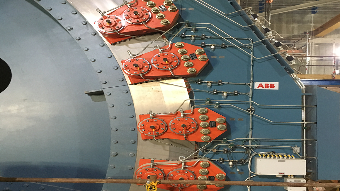
Each drum shaft is secured into position by means of bearing housings fitted with the appropriate bearings. The bearings are of the spherically seated, self-aligning split type and a force-feed oil lubrication system is utilized for lubrication of the bearings.
This lubrication system is installed on the Hydraulic Brake Station platform, EL. +71.500m.
The Production Hoist is equipped with a multi-channel closed-loop hydraulic brake system. The brakes are of the disk type, spring applied hydraulic pressure released brakes which is used to decelerate, stop or hold the hoist drum during normal and emergency hoisting operations.
Rope attachments is required for the purpose of connecting each rope end to the skip bail as well as allowing minor adjustments to the rope length. Six (6) adjustable-end headrope attachments, six (6) fixed end headrope attachments, and twelve (12) tail rope attachments are required for the Production Hoist.
East collar house
▪ Passage of equipment and materials to the reclaim conveyor lift well;
▪ Unloading the service cage and returning vehicles for re-loading;
▪ Oil / water separation;
▪ Raw water pumping
▪ Installing and removal of Service cage; and
▪ Emergency egress of personnel from personnel duct.
West collar house
▪ Final assembly and rigging of cage loads for delivery underground;
▪ Loading the service cage with routine and abnormal loads;
▪ Providing access to the headframe lift well for delivery or removal of large and heavy components; and
▪ House friction winch, foundations, and equipment for installing head and tail ropes of the production hoist.
South collar house
▪ Connected to an existing workshop building;
▪ Access for installation and removal of skip buckets and skip bails; and
▪ Washroom facilities.
General equipment
In general, each collar house shall be equipped with the following:
▪ Lighting (interior and exterior);
▪ Translucent panels for natural lighting;
▪ Heated by hydronic space heaters;
▪ Floors graded at 0.5 % away from the shaft;
▪ Drainage sumps and sump pumps;
▪ Insulated exterior cladding;
▪ Vehicle access doors; and
▪ Personnel access doors.
East collar house
▪ 15t electric overhead travelling crane;
▪ One power operated roll-up door;
▪ Crash barrier; and
▪ Two oil / water separators and one decant tank.
West collar house
▪ 40/5t electric overhead travelling crane;
▪ One power operated roll-up door;
▪ Two manually operated roll-up doors;
▪ Apertures for the ropes to pass into the structure during rope installation and changing;
▪ Foundations and cast-in frames for the friction winch and horizontal deflection sheaves;
▪ Foundations and cast-in frames for the rope reelers are situated North and South outside the collar house; and
▪ Crash barrier.
South collar house
▪ 40/5t electric overhead traveling crane;
▪ One power operated roll-up door;
▪ One manually operated roll-up door; (connecting the workshop and collar house)
▪ Male and female washrooms with one toilet and sink in each; and
▪ Crash barrier.